Serial Monitor guide
Using serial monitor
Note
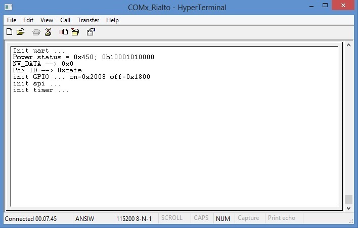
Startup messages are same in End-Node and Coordinator
Coordinator Serial Monitor
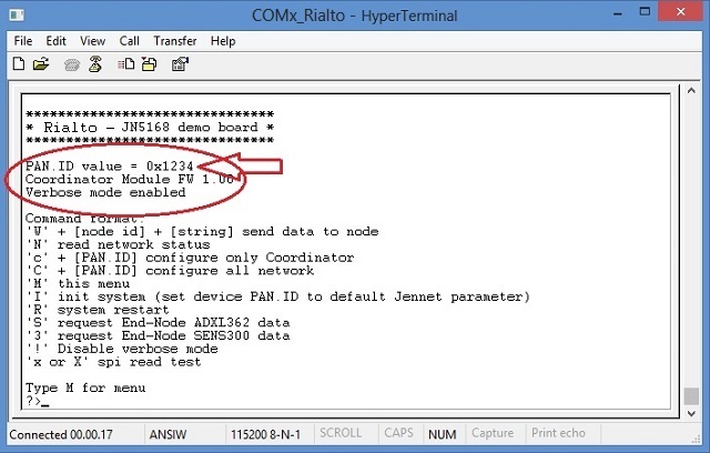
When Coordinator is power up, it sends (in sequence):
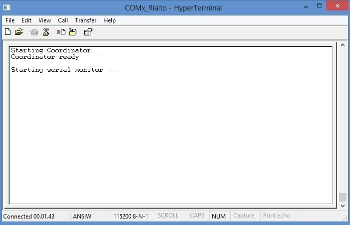
and after starts main menu as follow:
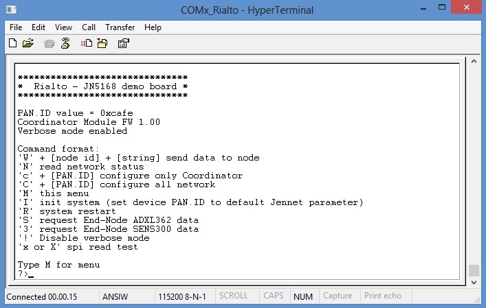
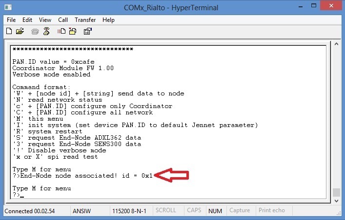
Serial Monitor main messages and commands
- End-Node detected and associated
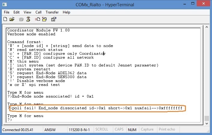
- End-Node poll fail and dissociated (details orange circled)
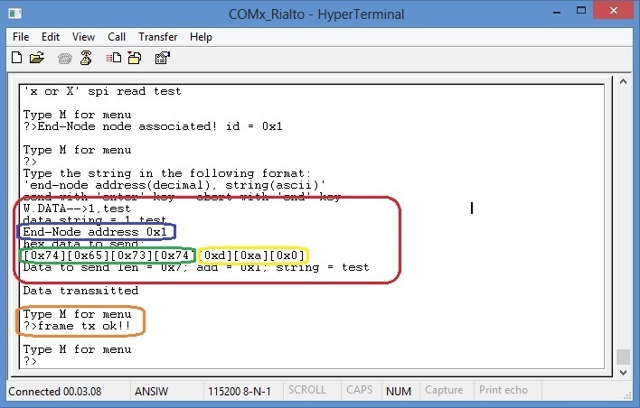
- Send data to End-Node (“W” command)
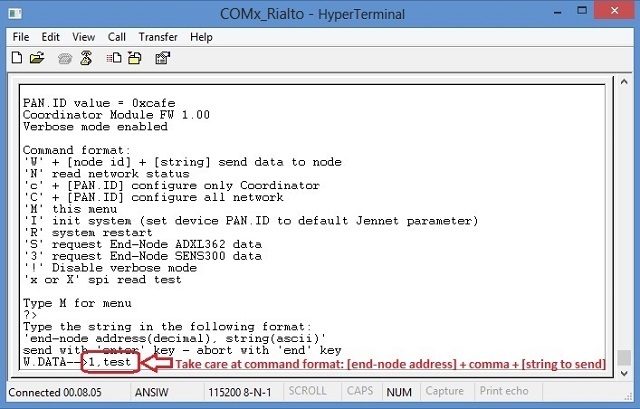
Important
In the Coordinator Monitor W command will send a “string” to a selected End_Node. You can see the received message inside End_Node Serial Monitor addressed by Coordinator
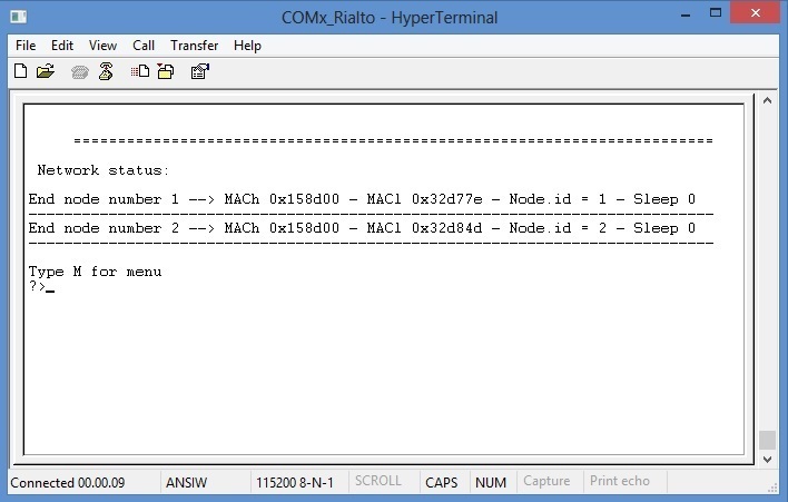
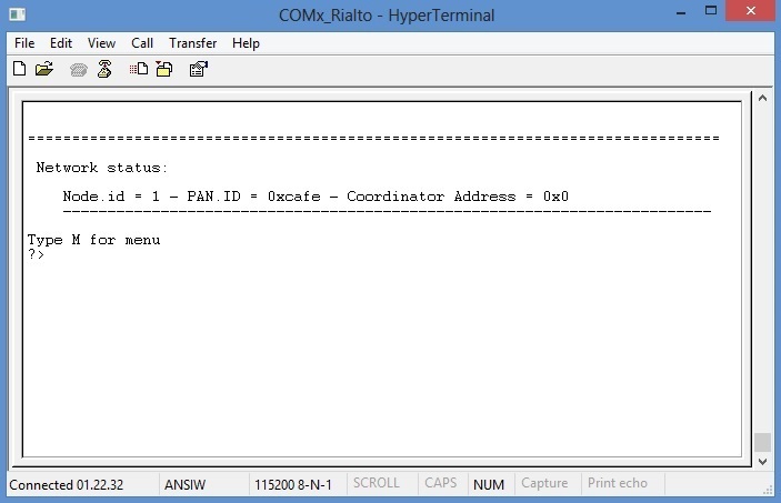
- Network status (“N” command)
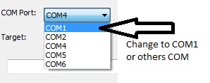
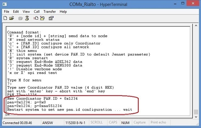
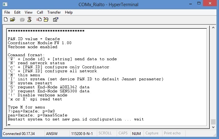
- Set Coordinator PAN.ID (‘c’ command)
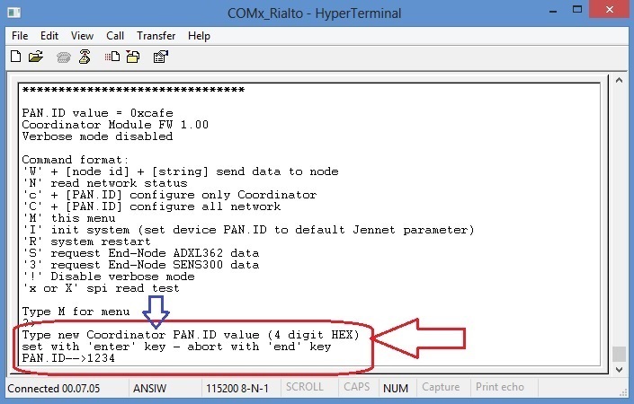
Please, note that ‘c’ command (lowercase) set only coordinator PAN.ID. To configure all network PAN.ID, use ‘C’ command (uppercase)
- Set network PAN.ID (“C” command)
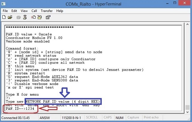
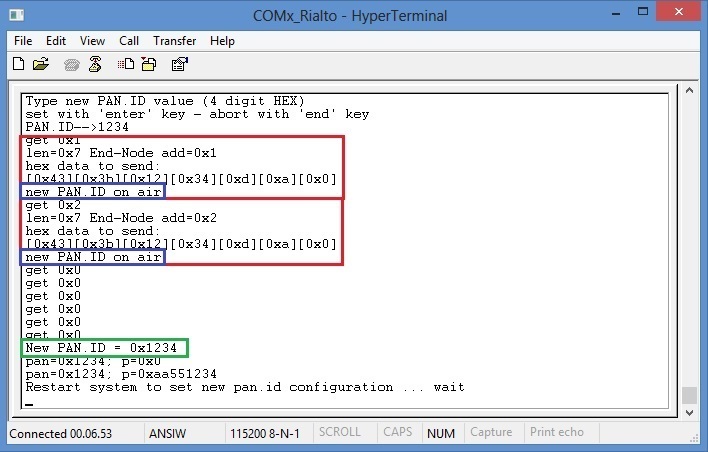
after system restart
- Default PAN.ID (“I” command)
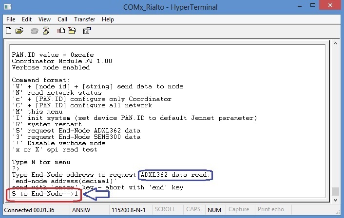
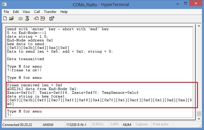
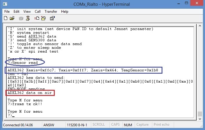
- Request End-Node ADXL362 data (“S” command)
- Received End-Node ADXL362 data
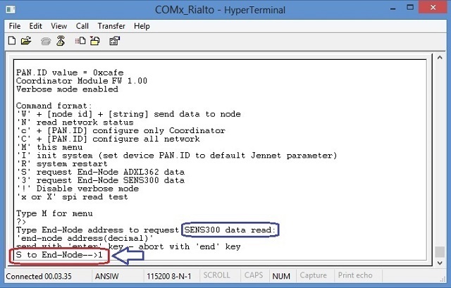
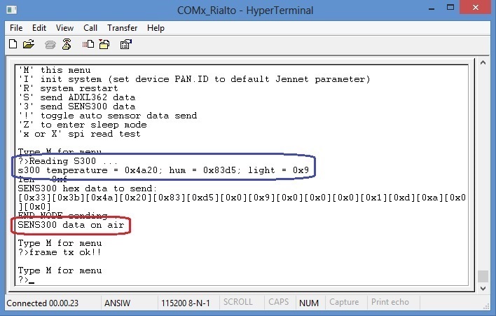
- Request End-Node SENS300 data (“3” command)
- Received End-Node SENS300 data
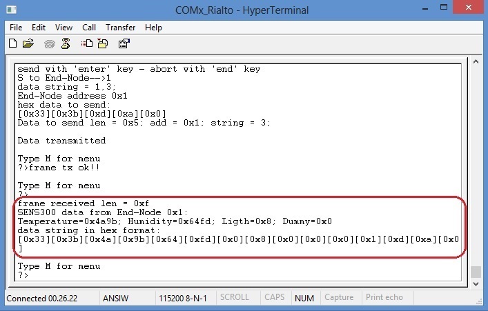
Important
All sensors data are transmitted in 32 bit HEX format, without any conversion in ASCII format. Values are position dependent, and must be read scanning the data string received
Note
In the Coordinator Monitor S and 3 command will answers a selected End_Node to read and send sensor data. You can see sensor data both in End_Node monitor and Coordinator monitor
- Disable verbose mode (”!” command)
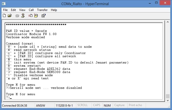
Note
In the Coordinator Serial Monitor, verbose mode is also set by SerizII. With verbose mode disabled, Serial Monitor messages are limited to data string and few other information. Check by yourself this operation mode.
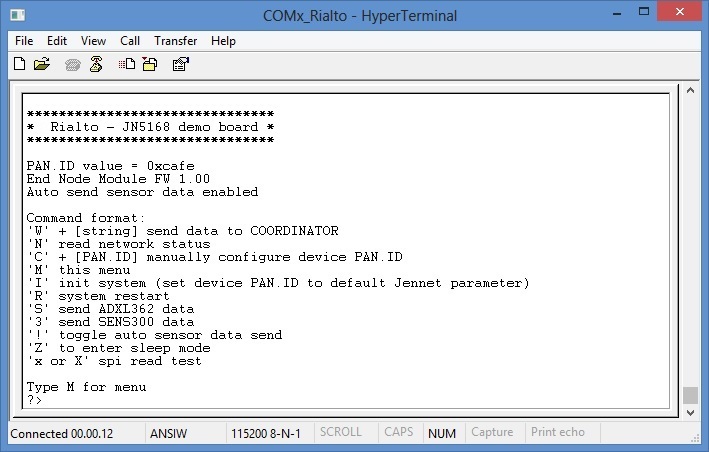
End-Node Serial Monitor
- End-Node main menu
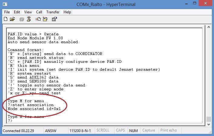
- Coordinator found, End-Node association
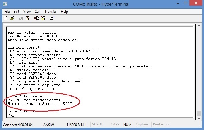
- Coordinator lost, End-Node dissociation
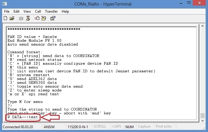
- Set data to send to Coordinator (“W” command)
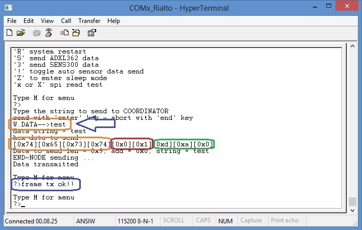
- End-Node network status (“N” command)
- End-Node ADXL362 data sending (“S” command)
- End-Node SENS300 data sending (“3” command)
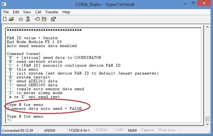
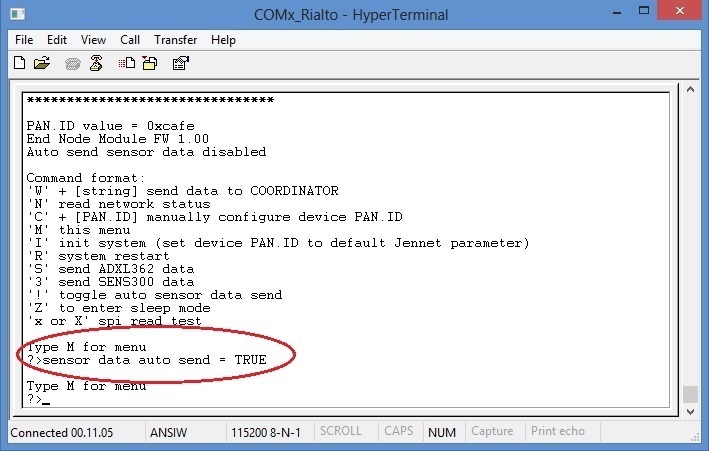
- End-Node Auto Send Sensors Data toggle (”!” command)
disable auto send
enable auto send
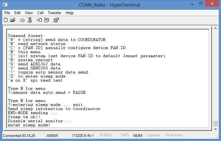
- End-Node Sleep Mode (“Z” command)
Important
In End-Node module, configuration command “C” perform only local device PAN.ID settings. If you use this command, End-Node will dissociate himself until it find a Coordinator with same new PAN.ID. The setting sequence is identical to that of the Coordinator command “c”(lowercase)